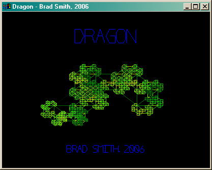
Dragon
In June of 2006 I wrote this demo. Mainly its purpose was for me to learn
how to use the OpenGL shading language, but it permitted me to explore several other ideas
which I had in mind. It uses the
SDL multimedia interface, and should actually be portable
to Mac and Linux architectures with little or no modifications. (I haven't yet tried because I don't
own any machines that use them.) You can download the demo here, and a description of how I
made it follows. Unfortunately, the source code for this program has been lost.
If you have any comments or questions, please e-mail them to me. My
address appears at the bottom of this webpage. I have prepared two
tutorials related to this demo about
Using GLSL with SDL
and
Hardware Texture Rendering. There
are other graphics tutorials and demonstrations available from my
main page.
|
A screenshot from the demo. Two dragons do battle with balls of fire.
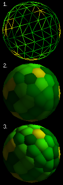
Three spheres:
1. Wireframe
2. Texture mapped
3. Bump mapped
Bump Mapping
My main goal with this demo was to learn the
OpenGL shading language
(GLSL) and apply it to some appropriate end, in this case
"bump mapping".
To decide how dark or light to draw a flat surface, you must figure out how much light should be
bouncing off of it, which is related to the angle of that surface to the source of light.
What bump mapping does is that for every point on the surface, you pretend that that the
angle of the surface is different according to a map you provide. (This map is called a
"normal map" and is used like a
texture map,
but instead of assigning colour, it assigns
a normal vector, which is a direction perpendicular to the intended surface.) This makes
the surface appear to be convincingly "bumpy". In my demo a normal map is applied to
the spherical dragon torso segments.
At the shading language level this is accomplished by at every vertex determining a
tangent to the surface (to simplify matters I did not pass the tangent as extra
vertex information, but rather let my vertex shader use knowledge of the geometry of
the sphere to construct its own tangent) and then between the tangent and given normal
create a third vector called the binormal, which combined with the other three form
an orthonormal basis (three
perpendicular unit vectors). From this I project the position of the light relative to
the vertex onto this basis, which will be interpolated by the fragment shader.
At the fragment level, a normal is looked up from the normal map texture which is
used directly in the standard
lighting equation
against the interpolated direction of light as seen by the vertex.
(I have prepared a tutorial: Using GLSL with SDL,
which includes code examples.)
Drawing a Sphere
I wanted render the sphere as a single
triangle strip,
which is the most efficient way to send an object to the graphic's card.
I also wanted the sphere to have a fairly even
tesselation
(of triangles that are roughly the same size) so that the
artifacts
related to tesselation would be uniform.
To attain even tesselation I divide the sphere into latitudinal circles
of points, and have each circle contain a number of points that is
proportional to its radius. After the number of points is determined
it is mostly a matter of proceeding from point to point in a zipper-like
fasion, but occasionally an extra point needs to be taken from the
top or bottom to account for the difference in numbers of points, which
is easily accomplished by doubling the previous point before
proceeding (creating a degenerate triangle, but preserving the
integrity of the strip).
To attain a continuous texture, I had to be wary of the fact that when
you go over a seam (at which one side of the texture's coordinates is 1
and the other side is 0), if you do not account for this you can have a
single triangle try to contain the entire range of the texture from 1
back to 0. One solution is to continually increment the texture coordinates
with wrapping implemented, so that every time over the seam, the coordinates
keep increasing, so instead of from 1 to 0.1, for instance, it would go 1 to 1.1.
Continually rendering the circles in a clockwise fashion would work, though at
extremely high tesselation this number might become so large as to produce inaccuracy
(but this is not likely practical, so the problem is moot). Instead, however, I took
a different approach of rendering each row of the sphere in the opposite direction of the
one before. Beginning clockwise, when I first hit the seam, I switch to
counter-clockwise for the second row and continue on in this matter until
finished.
To eliminate several problems, the circles at the poles were given
slightly greater than zero radius, and a number of points equal to the
circle next to them. This allowed nonzero coordinates for tangent
calculation in the vertex shader, and a way to have every point in the texture
map correspond to a unique point on the sphere.
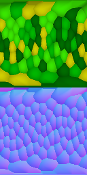
A texture map (above) and normal map (below).
Texture Generation
The scaly textures used are generated uniquely each time
the demo is run. The first step in generating such a texture was to model
the scales as a colleciton of 3D coordinates, all of them resting on a
sphere, each representing the centre of a scale.
To generate these points, I begin with a random set of vectors normalized
onto a
unit sphere.
After this is done, I perform a repeated process, each time
finding the nearest neighbour point to each point and moving it a small
distance away from that point before renormalizing it to the sphere. After
several passes, the configuration becomes stable and the points are
evenly distribued around the sphere. (Distributing points on a sphere is a
well known and interesting problem, for more discussion of this topic, see
The Mathematical Atlas.)
Once this collection of points is created, I can pick any point on the texture, figure out where that
texture will be on my tesselated sphere (see previous topic, "Drawing a Sphere"), and then finding
which point in my collection is closest to that point.
By taking the closest point, I can then construct a kind of
Voronoi diagram,
assigning the colour belonging to that point to this texture colour, but furthermore constructing a
paraboloid
scale shape that takes affect only in the area of the texture prescribed by the Voronoi diagram, the
gradient
of which will determine the normal at that point, used in the normal map. (The paraboloid is also used
to darken the edges of the scales in the colour texture map.) Note that the normal map appears mostly
blue, as the blue colour component of a normal map corresponds to the "up" direction.
The most difficult part of the problem was correctly mapping the points on the texture to points on
the sphere. For most of the sphere, the texture coordinate (s,t) is mapped directly to two
angles which are used to rotate a point to a position on the sphere. This mapping is what
causes the textures to appear a little "warped" when viewed as rectangles; the texture at the middle has to go all
the way around the equator of the sphere but the textures at the poles are stretched around much smaller circles, so
this mapping causes the scales at the ends to appear enlarged. There is an additional issue, since we are rendering
with triangles, that at the poles there is a "snipping" effect. Parts of the texture must be lost
in order to properly fold the triangles together at the top (an effect affectionately known as the "cat's ass").
In order to compensate for this, all of the points which fall between parts of the triangles are
mapped to the same point, which gives the edges of the texture a sawtooth appearance in the
texture map, but when applied to the sphere will elimiate all traces of the snipping. (See image below.)
A rendering of the dragon with low tesselation
but high scale density with its texture map in the background.
Note the sawtooth "snipping" at the top and bottom, which allows
the poles of the sphere (the dragon's nose) to appear continuous.
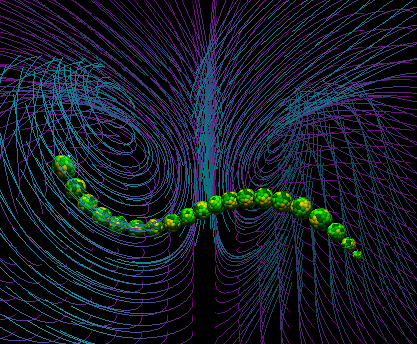
The dragon in its Lorenz attractor velocity field.
Chaotic Loops
I wanted to have the enemy dragon move in pleasant loops, but without
being predictable. I was drawn to the erratic yet well defined motion of
Lorenz attractors
as a solution to this problem. The attractor
is in this case a field of velocities; depending on where the dragon's
head is, these equations determine in what direction it will move:
dx = -10x + 10y
dy = 28x - y - xz
dz = -(8/3)z + xy
The numbers in these equations may be altered, but this particular
arrangment is the most famous and gives an optimal result for my
purposes (it is more balanced between the two attractive points than
other arrangements). This equation will keep the enemy dragon in orbit
of two fixed points, looping an undetermined number of times around each
before passing to the other side. (There is a fantastic Java applet
demonstrating various velocity fields at
Paul Falstad's Home Page.)
To keep the dragon from always looping around these two points, the
velocity field is occasionally rotated, changing the location of the
two points.(The centre of these two points is approximately
(x,y,z) = (0,20,0), so an
appropriate translation to move that centre point into view was also
used.)
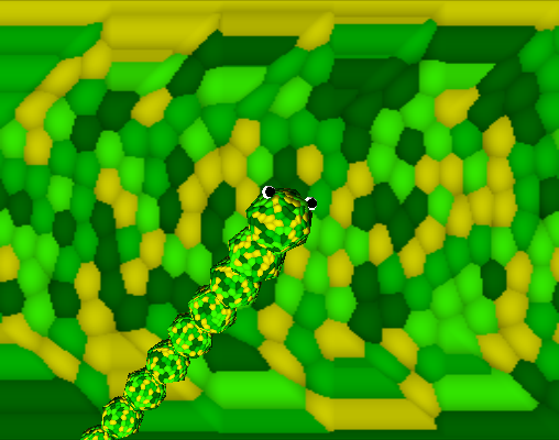
The MRCM fractal texture behind wireframe dragons.
Fractal Background
The layered background behind the dragons, constantly changing, is a
Multiple Reduction Copy Machine (MRCM)
fractal
outlined in the book
"Chaos and Fractals".
The process takes the texture
and makes three smaller copies of it (sometimes rotated or inverted).
This new image made out of the three copies replaces the original
texture and at the next iteration the process is repeated again.
Depending on the orientation of the copies, different fractal shapes
emerge. In my program, once the texture reaches a stable configuration,
the orientation of one of the copies is changed, and this texture
proceeds to mutate into the next fractal. In this way the continually
changing background is generated (the process can be seen more easily
by pressing T to select a view of the texture alone). There are
512 different fractals in this particular "family", which includes
a few versions of the well known
Sierpinski Triangle.
Producing such an image in graphics hardware was accomplished by
rendering the texture to the backbuffer, then using the copy to texture
function available in OpenGL to put that rendering in the texture.
Care must be taken to avoid losing pixels, or the fractal will not reach
stability and instead become a solid black image. Nearest neighbour
interpolation will throw away 3/4 of the pixels (as the copies are half
of the texture size in both dimensions), and linear interpolation will
reduce the intensity of each pixel to 1/4. Thus, linear interpolation
must be used with some method of amplification to attain a stable
configuration.
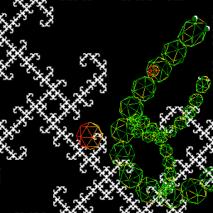
Another fractal appearing in this demo is the title screen's
Harter-Heighway Dragon
which can also be generated as an MRCM, but in this case is implemented as
a stack based traversal of a tree of the left or right turns that must be taken
to draw this fractal as a sequence of straight lines.
(I have prepared a tutorial: Hardware Texture Rendering,
which outlines the necessary code.)
Sound and Music
All of the sounds are synthesized using with simple oscillators
and filters using only integer math. The gameplay sounds are mostly
sine oscillators
of the 2nd order, meaning that knowing the last two positions of the
oscillator, you can determine its next position with only one multiply
and one subtract. Because of the periodic nature of sine waves, the
rounding errors will cancel eachother out, and the oscillator is
extremely stable. However, the overall amplitude has a low
resolution of accuracy, and it is difficult to change the frequency of
this oscillator while in motion because the second last position needs
to be recalculated. This difficulty manifests as a slight distortion
in the sine wave as its frequency changes in my demo, which I did not
consider an adverse effect, as this is, after all, a sound effect, and
for this purpose I thought the distortion was actually pleasant (it
adds just a little edge to the sound).
In the music, the melody and bass are saw wave oscillators (the implementation
is trivial, but ask me if you really need to know) with a R-C style lowpass
filter rounding off some of the harsher overtones. The bass drum was another
sine oscillator with clipping to give it more "thmp", and the snare drum was
a simple pseudo-random generator that was a kind of
linear
feedback shift register that could produce all possible values for a
16-bit integer except 0. This was a simple and efficient function:
1. Left shift the previous value.
2. If it overflows with a 1, XOR the new value with 0x1D87.
The lowpass filter:
If Z is a sample stored in the filter, I is its
current input, and O its current output,
1. The output sample O = Z * K.
2. Z is then changed to be equal to I + Z - O.
K is an attenuation factor related to the cutoff
frequency F and the sampling frequency Fs,
as K = 1 - e-2 * π * F / Fs.
(The preceding two processes were learned from the now out-of-print
book "Musical
Applications of Microprocessors".)
The music itself always follows a fairly strict pattern, but it
is never exactly the same, as it is continually generated from
fragments of a predefined source melody. The melody selects pitches
from a scale in the
Dorian mode
using just intonation, as
in the following table:
| D |
E |
F |
G |
A |
B♭ |
C |
D |
| 1/1 |
9/8 |
6/5 |
4/3 |
3/2 |
5/3 |
16/9 |
2/1 |
You may hear a short recording of sound from the demo here (384kB MP3).
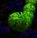
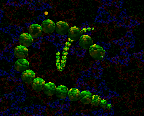
A very scaly dragon.
brad

rainwarrior.ca
2006-7-19